Wireless ski race timing
This is the specific use case for which this software was originally designed. Ullr allows for FIS-legal timing of Level 3 races or lower anywhere there is an internet connection. We’ll examine the setup for a homologated race step by step.
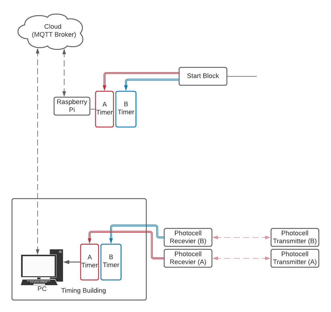
Wiring and signal flow for homologated ski timing.
At the start
Wiring
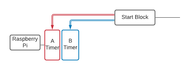
Wiring at the start.
The start block is connected by copper cable to two synchronized Time-of-Day timing devices, one for System A and one for System B. The System A timer is connected by serial cable to a computer running Ullr. This can be ANY computer capable of running Python applications and connecting to the internet. For example, the Raspberry Pi Zero W costs about $30 with a case and is around the size of a pocket knife. For the purposes of this tutorial we will assume that the start computer is a Raspberry Pi Zero W.
Ullr Configuration on the Raspberry Pi
Next we need to configure Ullr on the Raspberry Pi. This is fairly simple, as we only have one device to configure! Navigate to the Raspberry Pi web interface, either from the Pi itself or from another computer on the same LAN. See Running on a Raspberry Pi for more information on how to do this.
First we need to make sure the MQTT broker is set up correctly. See MQTT Broker Settings for more info on how to do this. Next, we need to set Ullr to connect to our System A timing device. Since this device is plugged directly into the Pi with a serial cable, it is a local device. Click the “Add Local Device” button in the “Configure” menu to pull up the add device dialog.
Give the device a descriptive name. For this example we’ll use a TAG CP540 as our timing device, so let’s name the device “CP540”. The next step is to select the port. We’re using a USB-serial converter cable in this example, so our port will be “/dev/ttyUSB0”. If you are using a serial connection directly to the Raspberry Pi your port name may be different. The CP540 runs at 9600 baud, so we’ll select that from the dropdown menu.
We’ll leave the mute checkbox unticked, since we are expecting to receive messages from this device. We’ll untick the “Accept Incoming” checkbox, since we don’t expect the timer to receive any messages (in fact, this is against FIS rules). This also reduces some of the processing overhead. We’ll leave the “Publish?” checkbox ticked as we are planning to access this device remotely.
When you’re finished, the settings should look like this:
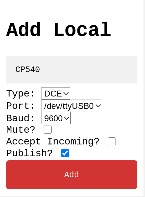
Settings to add the CP540 on the Raspberry Pi.
That’s all the configuration needed on the Raspberry Pi! When you’re done, make sure the CP540 device appears in the device window as shown below.
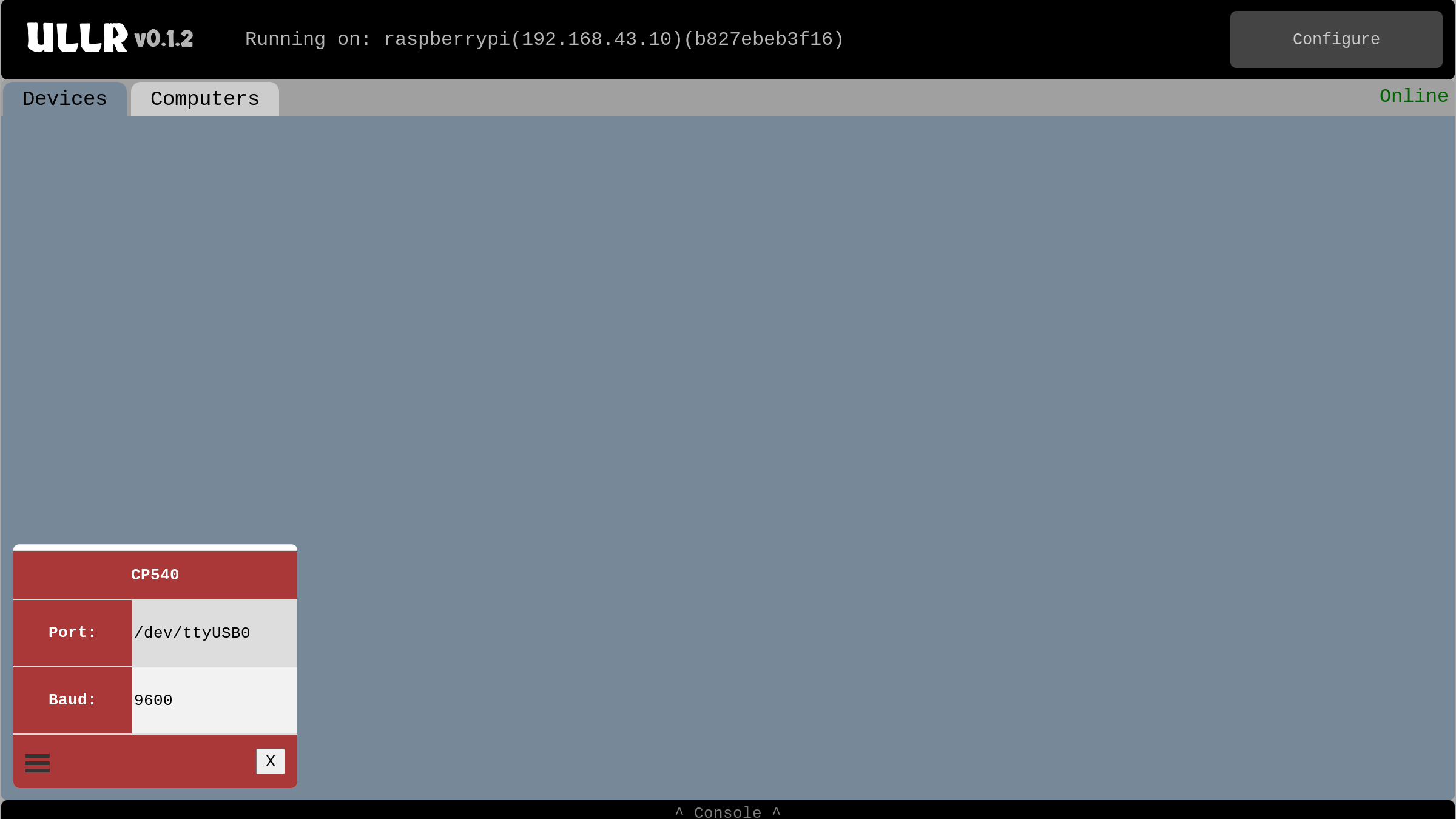
Device window with the 540 added.
If it’s not there, check the console for error messages and try again. Make sure to go to the “Configure” menu and save changes once you’re done. Finally, click the hamburger icon in the bottom left of the device to bring up the advanced menu. Write down the info for “Published name: “. This is what we’ll need to connect to this device from the finish.
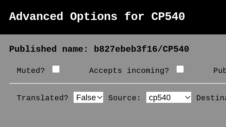
CP540 advanced menu showing published name.
Manual configuration
It’s also always possible (and possibly quicker) to edit the config file directly rather than using the interactive web configuration. When running as superuser (and we should be!) on the Raspberr Pi, the config file will be located at /etc/ullr/config.ini. We can achieve the same configuration by adding the following section to the file:
[CP540]
type = DCE
location = local
port = /dev/ttyUSB0
baud = 9600
published = True
mute = False
accepts_incoming = False
At the finish
Wiring
Wire the finish according to standard FIS rules. For example:

A FIS legal finish setup.
All that’s need to connect to the start is an internet connection and an Ullr installation. When we’re done, our software will be set up like this:

Signal flow within the finish PC.
Null modem setup
For Ullr to be able to connect to Split Second (or any other timing software), we’ll need to setup a virtual null modem. You can think of a null modem as two serial ports connected by a serial cable: Ullr will connect to one port, and split second to the other. A virtual null modem is just a software implementation of this. It is the pipe that carries information from Ullr to Split Second.
There are several virtual serial port software to choose from, but for Windows the com0com project is stable and completely free and open source. A signed installer is available from the Alge website here: com0com (signed).
Once com0com is installed, we’ll need to run the configuration to add a linked pair of com ports. You can choose any two port numbers you like, as long as they’re not already in use. I like to use COM50 and COM51.
Ullr configuration on the finish PC
Next we’ll need to get Ullr setup on the finish PC. We have two devices to add this time: our start timer (a remote DCE device), and Split Second (a local DTE device).
First, navigate to the web interface (localhost:5000) and open the “Configure” menu. The first step is to set the MQTT broker settings. They need to be the same settings as the Raspberry Pi at the start!
Next we’ll add our remote start timer, using the information from the previous step. Click the “Add Remote Device” button to bring up the dialog. The device name can be anything that makes sense to you. For this guide we’ll use “Start Timer”. The Host ID/Device ID field is where we’ll put the “published name” from the previous section. In our case it’s “b827ebeb3f16/CP540”.
The next field determines how late messages will be handled. If there is an interruption in internet connection, it’s possible that messages from the start will arrive late. If they arrive too late it will cause unexpected behavior in Split Second. For example, a start impulse that arrives after a finish impulse or a start impulse that arrives out of order will both result in trouble. Let’s imagine we are running a GS on a 30s interval. An on-time arrival setting of 25s should be safe. Any message that arrives after 25s will appear in the late messages list and can manually be sent to Split Second later on. For more info on late messages, see Handling Late Messages.
Since our start timer is a DCE device, select DCE from the dropdown.
The next two fields are already familiar to us, and we should use the same settings we used on the Raspberry Pi at the start. Both “Mute” and “Accepts Incoming?” should be unticked.
When you’re done the settings should look like this. Click the Add button.
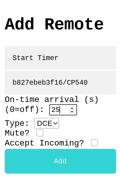
Settings to add our remote start timer.
Next we need to add Split Second (or a different timing software). Click the “Add Local Device” button.
Since we’re using Split Second software in this example, let’s name the device “Split Second”. Since it’s a piece of software, its a DTE device. Select DTE from the dropdown.
For the port, choose one of the ports in your virtual null modem pair. In our example we paired ports COM50 and COM51, so lets choose COM50. We’re working with a CP540, so we’ll again choose 9600 baud.
Now we have our familiar checkboxes. Since Split Second isn’t sending any messages to the timer (and FIS doesn’t allow it anyways), we can go ahead and tick the “Mute” box. We’ll be sure to leave “Accepts incoming?” ticked as our entire goal is to send Split Second messages. We’ll go ahead an untick the “Publish?” box as there is no need to access this device directly from the cloud.
When you’re done, the settings should look like this. Click the Add button.
FIGURE here
We should now have two devices configured and visible in the device window, one under each tab. If you ran into any trouble check the console for error messages and try again.
At this point it’s a good idea to send some test impulses from the CP540. They should appear on the virtual “timing tape” above the “Start Timer” device.
Manual configuration
Again, it’s possible to add these settings to the config file directly rather than using the web interface. On Windows the config file will be located in a subdirectory of your home folder. For example, my config file is located at C:\users\zhenry\.config\ullr\config.ini. The same configuration as above can be achieved by adding the following sections:
[Start Timer]
type = DCE
location = remote
topic_name = b827ebeb3f16/CP540
on_time_max = 25
mute = False
accepts_incoming = False

[Split Second]
type = DTE
location = local
port = COM50
baud = 9600
published = False
mute = True
accepts_incoming = True
Split Second configuration
All that’s left to do is configure Split Second. This is similar to the usual Split Second configuration, but this time we have two timers: our finish timer that’s wired to the timing computer with a serial cable, and our start timer that is connected by Ullr and a virtual null modem.
Configure the hardwired finish timer the way you usually do.
Then, go to the second timer tab and configure the remote start timer. Choose the device name and baudrate as usual. For the port, select the other end of the virtual null modem. In our case, our null modem connects ports COM50 and COM51. We connected Ullr to COM50, so we’ll connect Split Second to COM51.
Note that this only works with timing programs that support multiple timers, such as Split Second’s National/FIS and Vola. Using Ski Club or another program that only supports one timer? No problem! Read on to the next section.