Advanced Ski Racing
What if we’re using a program like Split Second’s Ski Club that only supports connecting one timing device? What if we want to use 3 or more timing devices to add wireless split times? What if our devices are not all the same? Ullr can make it happen.
This section expands on the previous section, Wireless ski race timing. We’ll start with the same basic signal flow, and add to it where necessary.
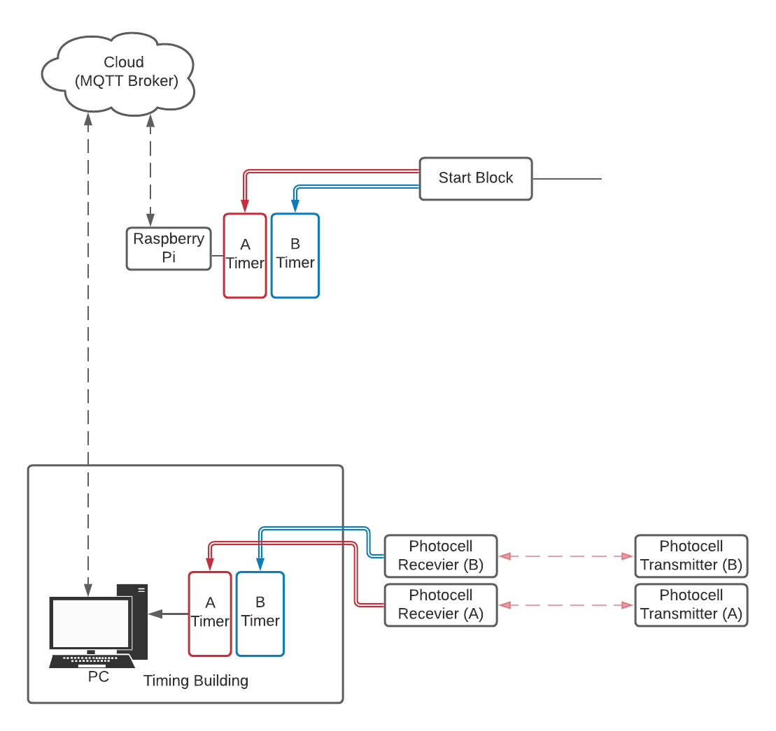
Wiring and signal flow for homologated ski timing.
Connecting multiple timers to Ski Club
In our previous section we setup Ullr for wireless ski race timing. But there’s one potential problem with our setup: it depends on connecting two timing devices to our timing software. NATFIs supports this, but not all timing software does. In this section we’ll setup wireless timing in Ski Club, which only supports one timing device.
The wiring at the start and finish remains the same as in the previous section, as does the configuration of the Raspberry Pi and Ullr at the start. We just need to make some software changes in the finish.
Ullr configuration for Ski Club
We’ll use the same Null modem setup as in our previous example.
All that changes is the flow of serial information inside the computer.
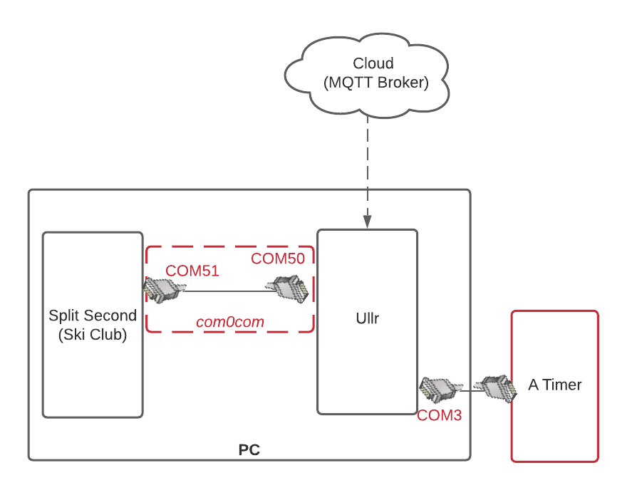
Signal flow within the finish PC.
What changed from our previous setup? Instead of connecting the System A finish timer directly to the timing software, we connect it to Ullr. Ullr will intercept both the start impulses from the MQTT broker (the cloud), and the finish impulses from the physical serial port. It will then pass all of these impulses on to our null modem, which is connected to Ski Club. As far as Ski Club is concerned, it is connected to one timing device.
We need to update our Ullr configuration to reflect this change. All we need to do is add a local DCE device representing our physical timer, in addition to the remote device we added in the previous step for our start timer.
Open the Configure menu and click Add Local Device. Let’s call our device “Finish Timer”, and say it’s connected to COM3 at 9600 baud. It should be unmuted and set to not accept incoming messages. There is no need to publish this device.
Click the Add button. You should now have two devices in the Devices tab: the remote start timer, and the local finish timer. You should also have Split Second under the Computers tab from the previous section.
You’ll end up with a config file similar to this:
[Start Timer]
type = DCE
location = remote
topic_name = b827ebeb3f16/CP540
on_time_max = 25
accepts_incoming = False

[Finish Timer]
type = DCE
location = local
port = COM3
baud = 9600
published = False
accepts_incoming = False

[Split Second]
type = DTE
location = local
port = COM50
baud = 9600
published = False
mute = True
There are a couple things to consider with this setup. Since Ski Club doesn’t know that it is reading from two timing devices, not one, it is up to you to setup input mapping in a safe and logical way. It is important not to allow channel numbers to conflict or overlap. Ski Club has no way of differentiating between an impulse on channel 1 of the remote start timer or an impulse on channel 1 of the physically connected finish timer. It may be necessary to shift channels, which will be described below.
Adding additional timers
There may be times when it’s convenient to connect even more than 2 timers to our timing software. Consider the setup with a wireless speed trap below:
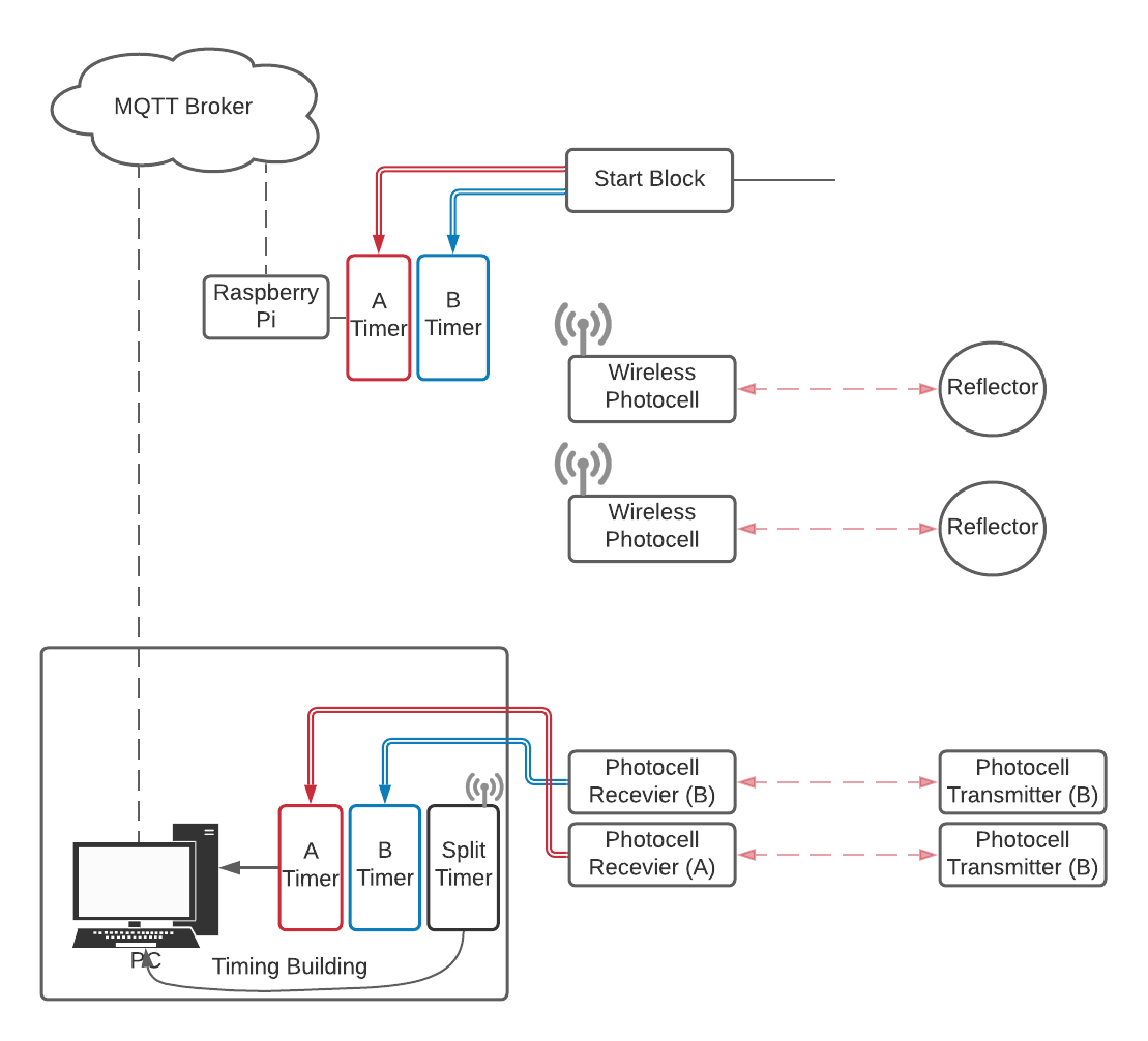
Signal flow with a homologated wireless start and non-homologated speed trap.
We’ve kept our homologated wireless setup at the start and our hardwired finish timer, but added a third timer to handle a speed trap, for this example a Microgate Racetime2. Since there are no homologation requirements for splits and speed traps it’s possible to use a radio transmitted photocell such as the Microgate.
However, even Vola and NATFis software only allow the connection of 2 timers, and now we have three. We can set Ullr up to send all of the timing information over one port, as below.
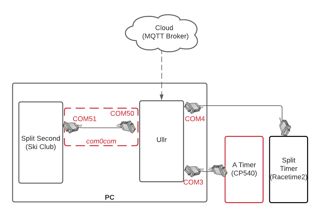
Signal flow within the finish PC with multiple timers.
It’s just a matter of configuring Ullr correctly. For this example, we have one remote device, our start timer. We have two local devices connected to the timing PC with a serial cable: the finish timer and the split timer. Ullr will intercept messages from all 3 devices and pass them on to Split Second through our null modem.
If we configure Ullr through the Web UI, our device window will look something like this:
FIGURE here
We could also just manually enter the info into the config file. We’ll end up with something like this:
[Start Timer]
type = DCE
location = remote
topic_name = b827ebeb3f16/CP540
on_time_max = 25
accepts_incoming = False

[Finish Timer]
type = DCE
location = local
port = COM3
baud = 9600
published = False
accepts_incoming = False

[Split Timer]
type = DCE
location = local
port = COM4
baud = 9600
published = False
accepts_incoming = False

[Split Second]
type = DTE
location = local
port = COM50
baud = 9600
published = False
mute = True
This example assumes that all three of your timers (start, finish and split) are the same. Since we are sending information from all three to Split Second over a single serial port, Split Second will assume that all of the messages are in the same format. Mixed format messages will cause errors.
What if all 3 timers aren’t the same? How can we get the messages into a uniform format that Split Second can understand? That’s where translation comes into play.